Mechanism Design Case Study
Boat Propulsion Without the Propeller
Boat propellers are dangerous to marine life, so this project replaces the propeller entirely. A four-bar linkage sweeps a flexible silicone fin through a controlled 40° arc, much closer to how a fish swims. The linkage geometry was sized on paper first and then verified with motion simulation.
The Idea
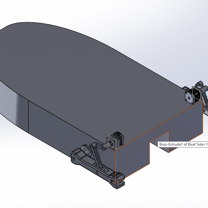
The assignment asked for a boat propulsion system that avoids traditional propellers because of the harm they cause to marine life. Our answer mounts a four-bar linkage on the stern and lets it sweep a fin instead of spinning a blade.
The interesting part is that nothing about the fin's motion is left to chance. The sweep angle, the anchor point, and every link length came out of geometric construction before the CAD model existed.
Groundwork: Learning to Trust a Motion Study
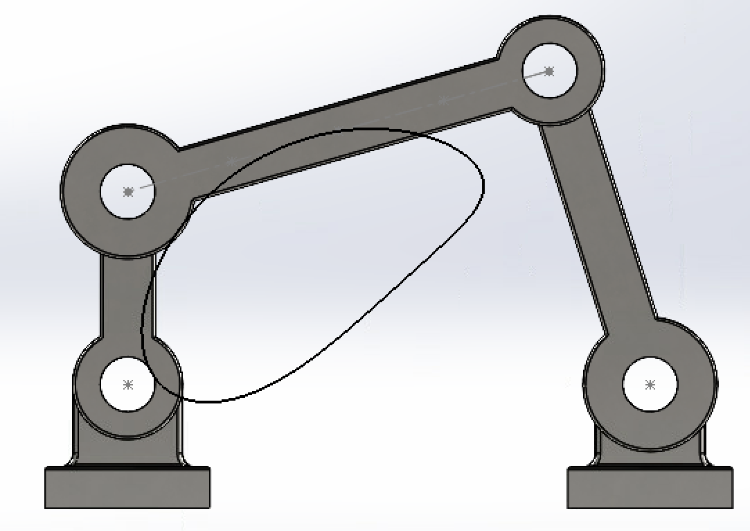
Before the boat, the class built and analyzed a plain four-bar linkage in SolidWorks, and the first lesson was humbling. Our initial assembly reported minus 8 degrees of freedom. Standard mates had over-constrained the mechanism into a statically impossible object. Rebuilding the joints with revolute, cylindrical, and spherical mates got it to 3 moving parts and exactly 1 degree of freedom, which is to say, a mechanism that actually moves.
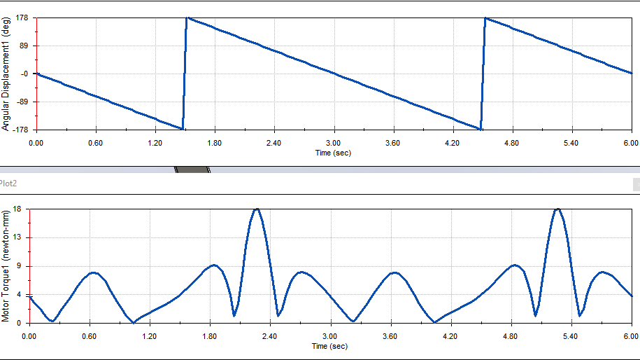
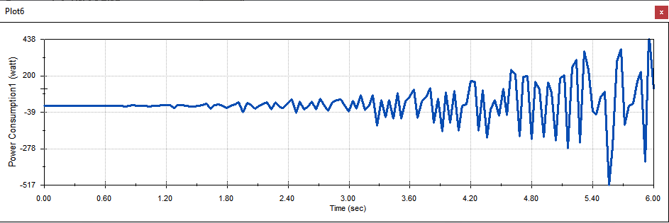
With the model healthy, we traced the coupler midpoint's path and exported it to CSV, then pulled torque, bearing-force, and power curves from the motion study. The torque peaks landed where the crank pushes through its positions of least mechanical advantage. The power plot even dips negative in the moments when the mechanism's own momentum drives the motor instead of the other way around.
Sizing the Fin Motion
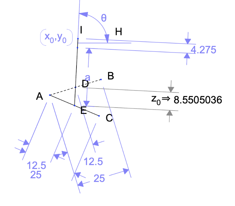
The fin needed a consistent sweep between two positions with a fixed anchor point. We chose a 25 cm rocker with the extension fixed at its 12.5 cm midpoint and a 40° sweep angle, then worked backwards. Perpendicular-bisector constructions through the two extreme positions locate the pivot, and half the distance between the extremes sets the crank length.
It's classic graphical linkage synthesis, the ruler-and-compass kind, and it answered every dimension before the simulation ever ran.
The Parts
The mechanism breaks down into a crank, a coupler extension, a rocker that carries the fin, and a stern bracket that ties it all to the hull.
Why a Silicone Fin
A rigid paddle just shoves water around. A flexible silicone fin bends through each stroke the way fish and other marine animals do, producing a slow, controlled paddling motion that moves the boat while staying far gentler to anything swimming nearby than a spinning blade ever could.
What I Learned
- Degrees of freedom are a diagnostic. A reading of minus 8 means the CAD model is lying about the physics, and the mates are usually the culprit.
- Graphical synthesis answers how long each link should be before any simulation runs.
- Negative power in a motion study is real information. It shows exactly when the mechanism back-drives the motor.