First-Year Build · Solo Documentation
The First Thing I Built That Wasn't a Kit
A portable room-temperature monitor. An Arduino reads a TMP36 sensor, shows the temperature on an LCD, and fires a red LED and buzzer when the room leaves a set range. It was the first project I took the whole way: sketches, CAD, breadboard, solder, enclosure, test.
The Goal
Build a practical, low-power, portable device that monitors room temperature and makes it obvious when something is wrong. That meant a readable display, an unmistakable alarm, and battery power so it can sit in any room.
I also wanted to build it properly: durable, replicable, and not a tangle of jumper wires in a shoebox.
From Sketch to Solder
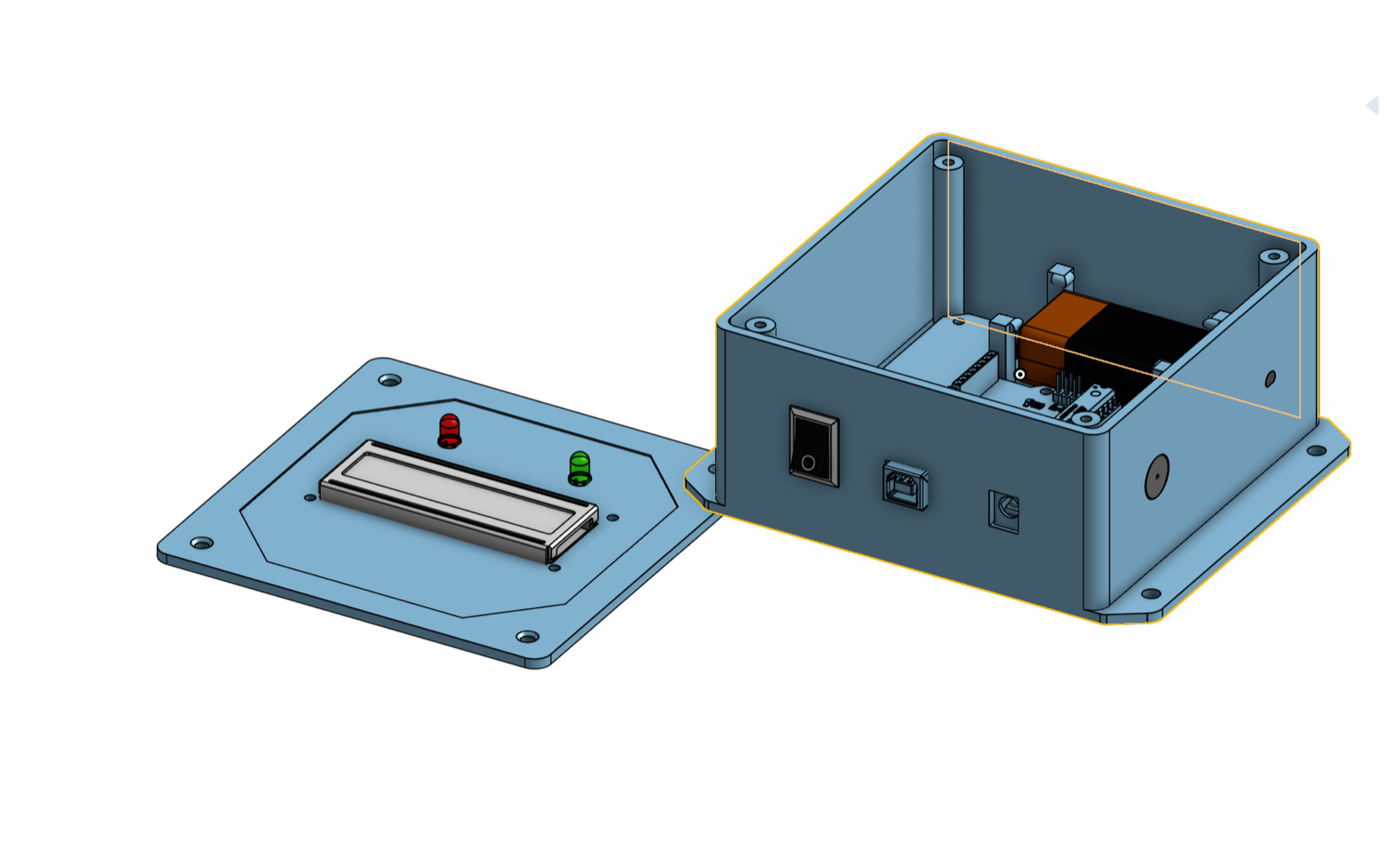
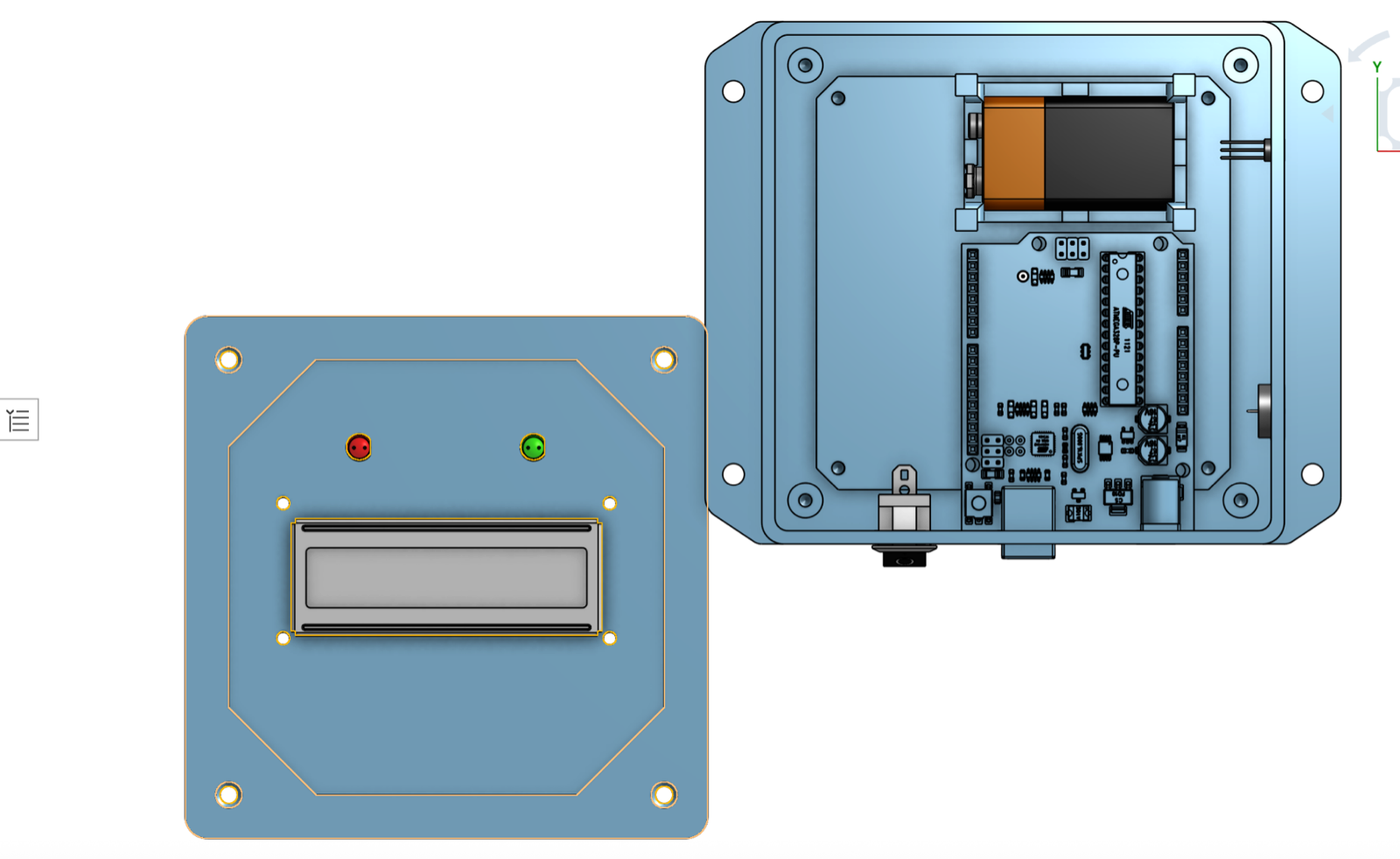
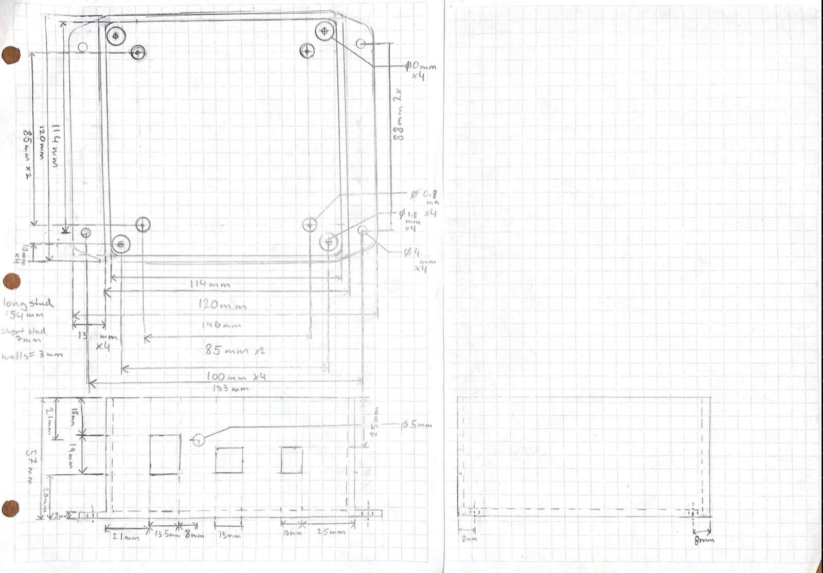
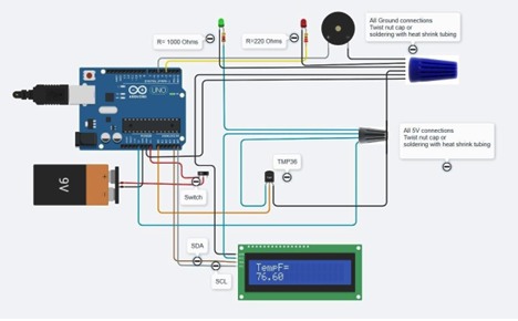
Every component got measured by hand and sketched before anything was placed: Arduino Uno, TMP36 sensor, 16×2 I2C LCD, piezo buzzer, LEDs, switch. Then everything was arranged in a CAD model of the ABS enclosure, including a 3D-printed holder that keeps the 9V battery from rattling around. The circuit came to life on a breadboard first, and once it behaved, I soldered the connections for a permanent build.
The electrical details got real attention for a first project. The 22 AWG wire was chosen against its current capacity (the whole circuit draws 74 to 88 mA, far below the limit), the LED resistors were sized from measured voltage drops, and the battery-life estimate of 7.8 to 9.3 hours came from the actual current draw rather than a guess.
Does It Work?
Yes. Readings tracked a standard thermometer within about ±1 °F, the alarm fired reliably outside the set range, and the enclosure kept everything solid. The alert range was set at 80 to 90 °F on purpose: the test room sat at 70 to 75 °F and I could only heat the sensor, not cool it, so a higher window let me demonstrate behavior on both sides of the threshold.
The one real limitation is battery life, since a 9V only lasts a few hours. Long-term use wants a wall adapter or a rechargeable pack.
What I Learned
- The path from breadboard to soldered build is where a circuit becomes a product, and where half the wiring bugs surface.
- Measure, don't assume. Sizing resistors from measured LED voltage drops taught me more about circuits than any diagram.
- Design the test before the demo. Picking an alert range I could actually drive the sensor through made the evaluation meaningful.
- This project set the template every later one followed: sketch, model, build, measure.