Bellee: the Handwave Doorbell
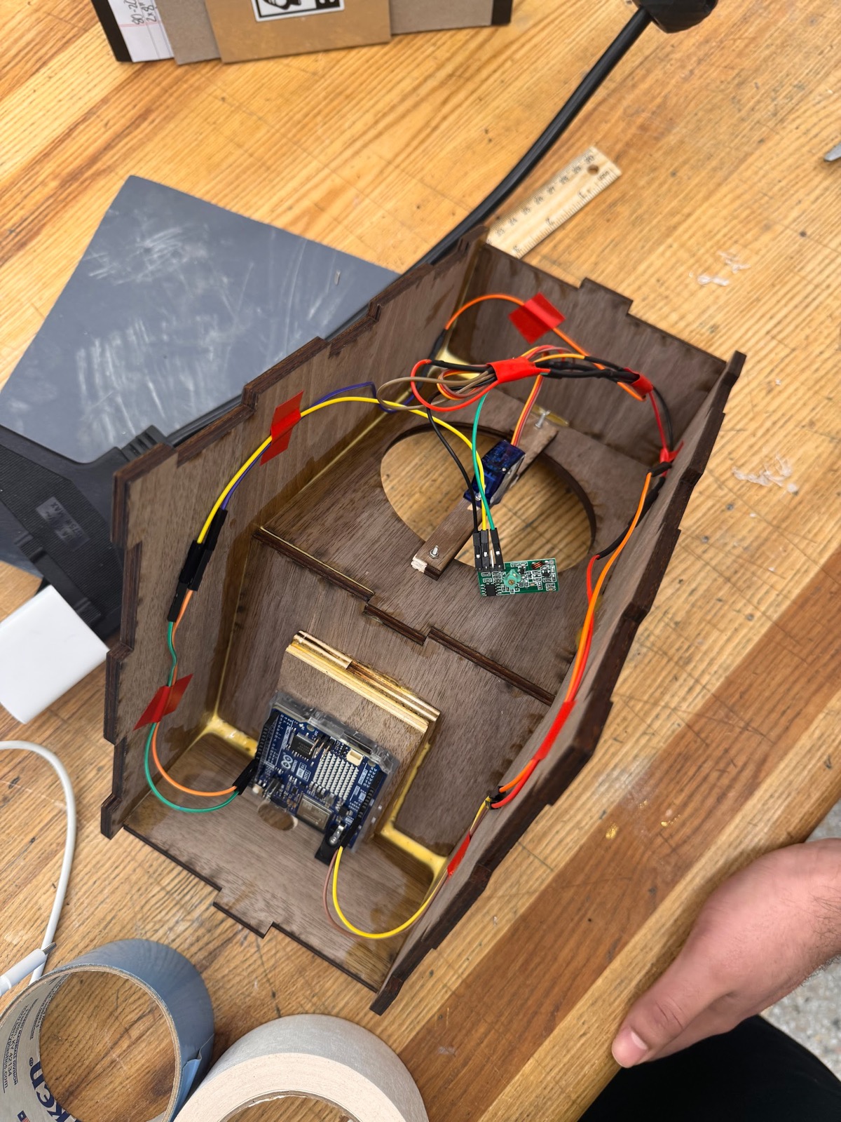
A retro-style doorbell you trigger with a wave. An IR sensor sends an RF signal to a servo that rings real wind chimes. Detection accuracy went from 76% to 94% through iteration.
Read the Case StudyOliver Zeman · Mechanical Engineering · Boston University
I've built a doorbell that rings real wind chimes when you wave at it, a bridge truss that survived 138 redesigns, and a machine that plays out a tennis rally by itself. This site shows how each one got made.
About
My coursework at BU has taken me from soldering my first Arduino circuit to designing linkage-driven propulsion systems and multi-motor motion platforms. Along the way I've built with 3D printers, finger-jointed plywood, breadboards, soldered protoboards, T-slot rail, and timing belts.
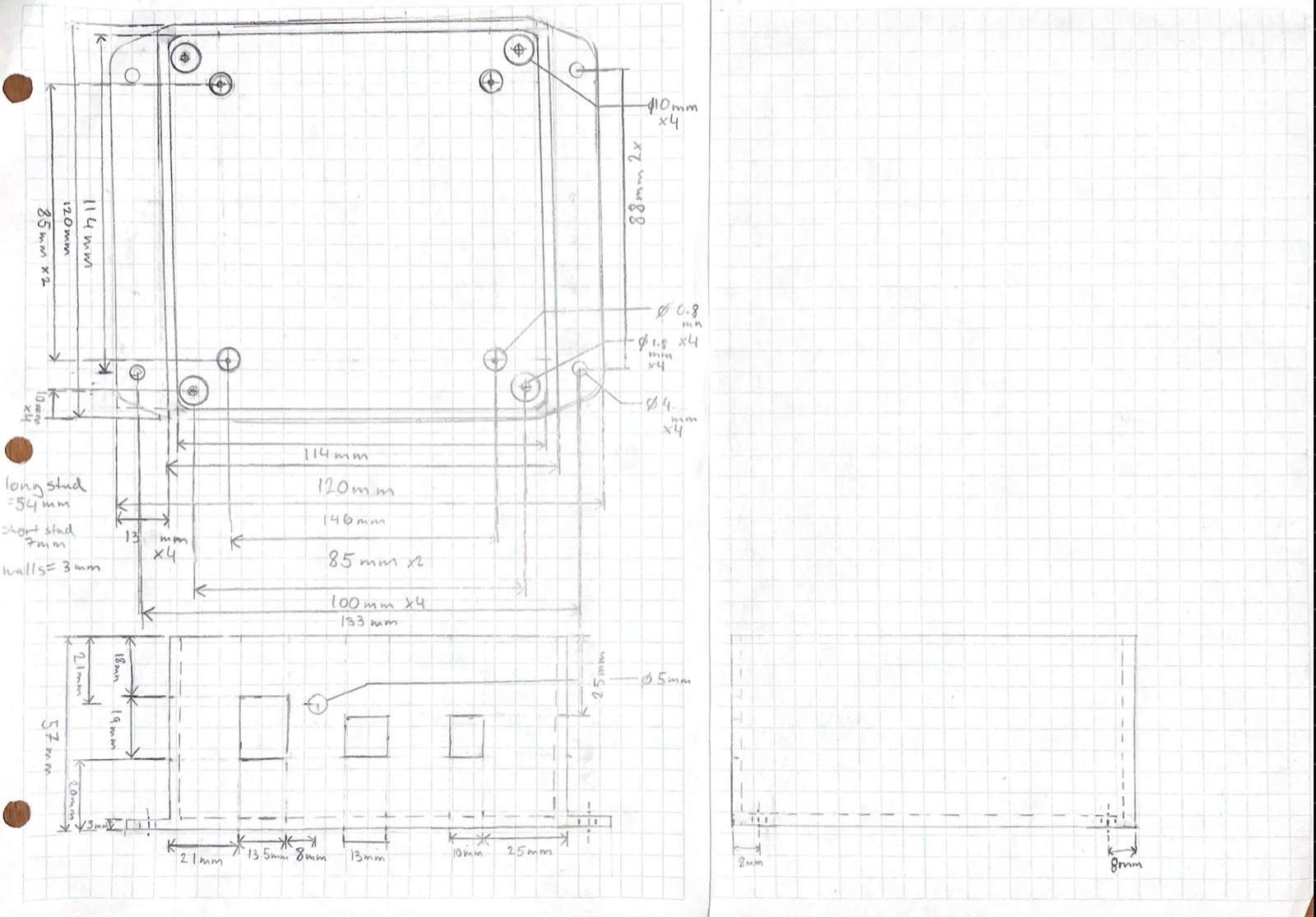
A few habits stuck. I write down the target metric before designing anything. I explore lots of options on paper, where mistakes are cheap. And ever since studying the Hartford Civic Center roof collapse in my mechanics course, I refuse to trust a simulation that hasn't been checked against the real thing.
Projects
Six projects from three years of engineering coursework. Each page walks through the goal, the design decisions, the build, and what the testing actually showed.
A retro-style doorbell you trigger with a wave. An IR sensor sends an RF signal to a servo that rings real wind chimes. Detection accuracy went from 76% to 94% through iteration.
Read the Case Study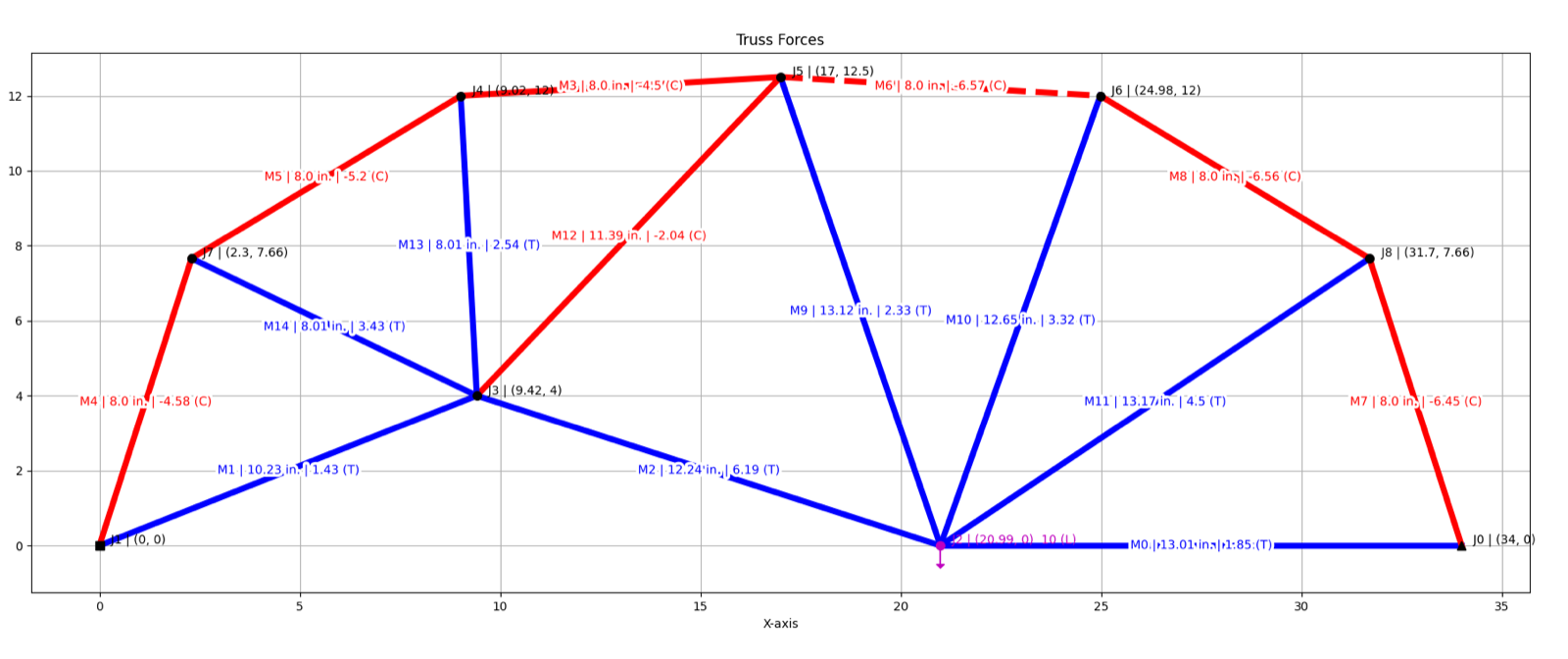
A custom MATLAB solver let us test 138 bridge variants for load-to-cost. The final arch design carried a predicted 91 oz, which beat our first optimized attempt by 19%.
Read the Case Study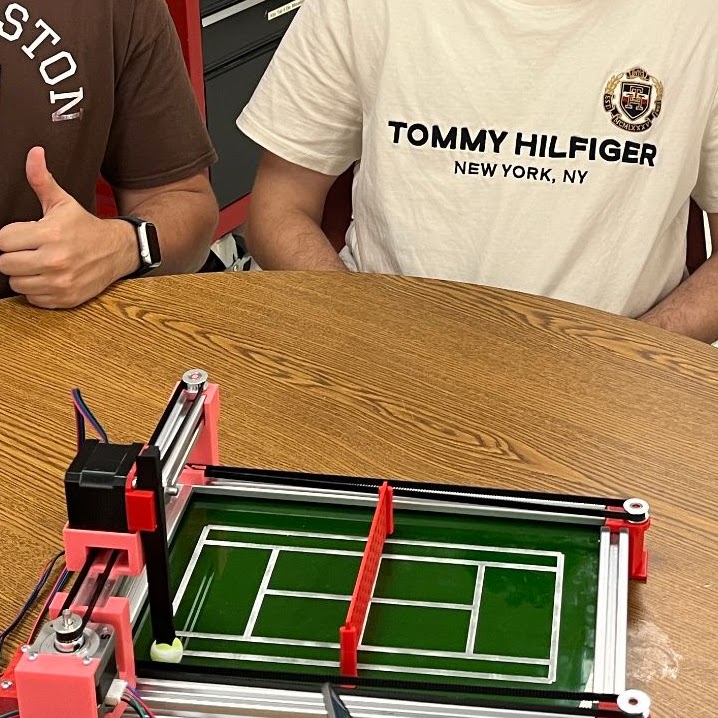
A stepper-driven Cartesian machine that replays a tennis rally: 3D-printed brackets on T-slot rail, GT2 belts, and an Arduino Mega running roughly eight programmed shots.
Read the Case Study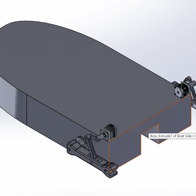
A four-bar linkage sweeps a silicone fin through a 40° arc, the way a fish swims. Sized on paper with classic linkage geometry, then verified in SolidWorks Motion.
Read the Case Study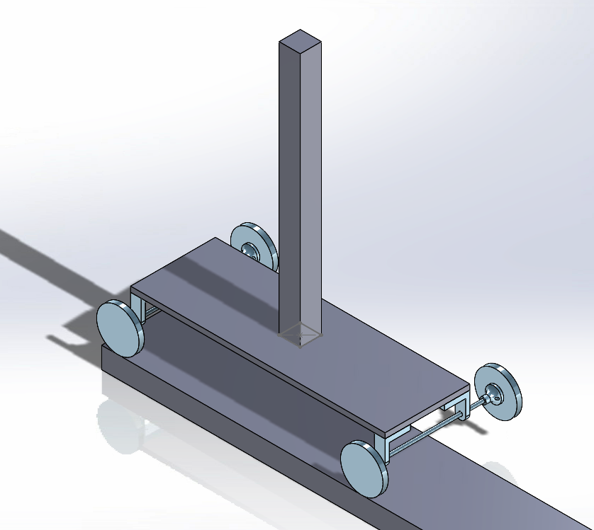
How fast can you accelerate a 12-inch bar without tipping it? Theory said g/12, about 0.8175 m/s². Simulation said 0.817. We built the cart around that number.
Read the Case Study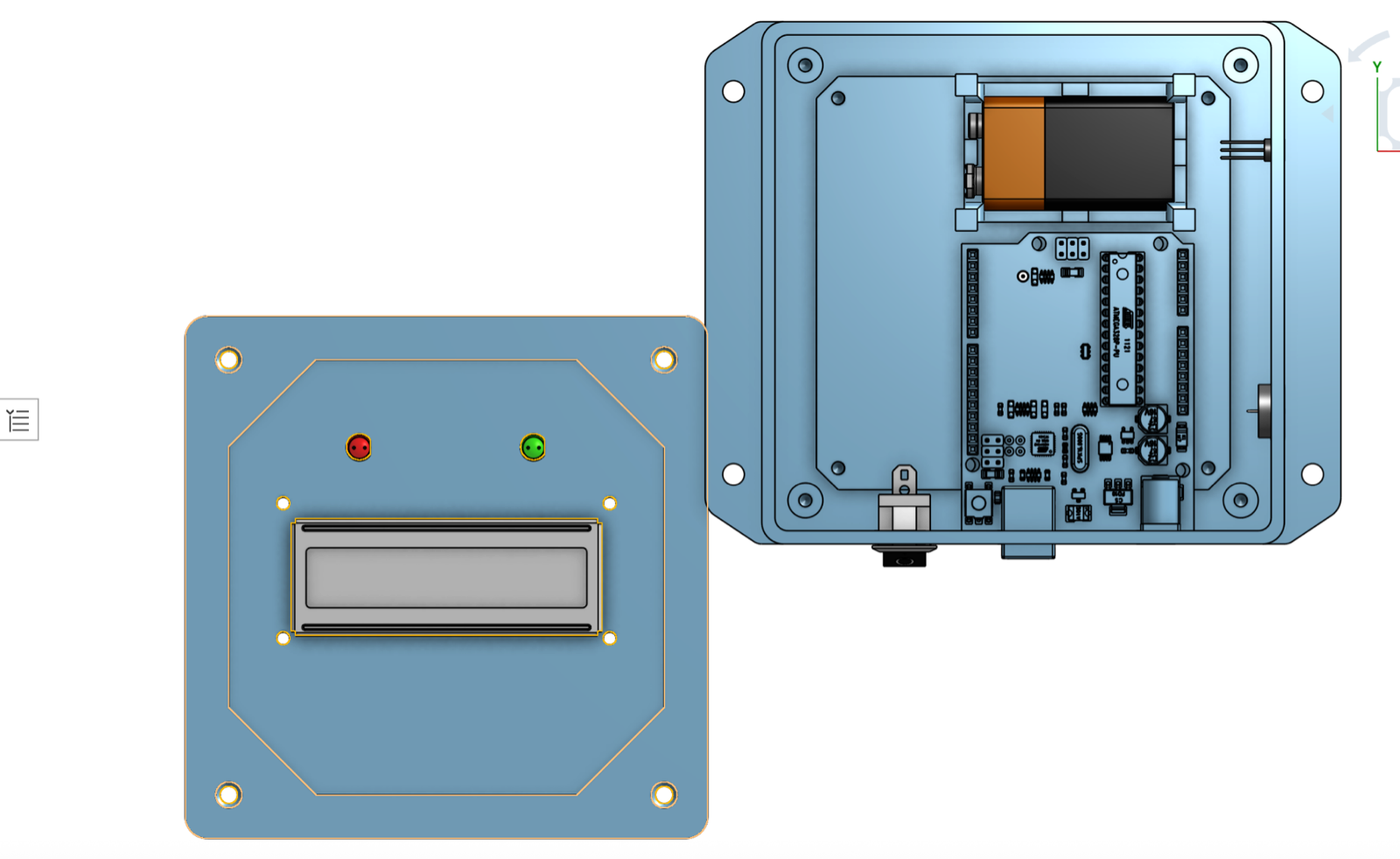
My first full build: an Arduino temperature monitor taken from hand sketches and CAD to a soldered, enclosure-mounted prototype reading within about ±1°F of a reference.
Read the Case StudySkills & Tools
Everything listed here shows up in at least one of the projects above.
Process
The same loop shows up in every project, whether it's a doorbell or a truss.
I write down the number that will judge the design before designing anything. For Bellee we set measurable objectives up front: detection accuracy above 95%, response under half a second, setup within 15 minutes. For the truss it was a single ratio, load over cost.
Morph charts, design archetypes, quick geometry constructions. We ran 138 truss variants through our MATLAB solver before committing to one, because a weak idea costs far less on paper than it does in hardware.
CAD assemblies and motion studies predict forces, torques, and clearances, and those predictions get checked. Our speed cart's simulated tipping limit of 0.817 m/s² matched the hand calculation (g/12, about 0.8175 m/s²) almost exactly, so we trusted it.
The prototype settles every argument. Bellee's hand detection started at 76%. Repositioning the sensor and adding an antenna brought it to 94% over 50 trials and stretched the RF range past 8 meters.